Table of Contents
- PCB Full Form: Introduction
- PCB Full Form: History
- PCB Full Form: Features
- PCB Full Form: Types
- PCB Full Form: Advantages
- PCB Full Form: Disadvantages
- PCB Full Form: Limitations
- PCB Full Form: Characteristics
- PCB Full Form: Layers & Components
- PCB Full Form: Manufacturing Process
- PCB Full Form: Conclusion
- PCB Full Form: FAQs
PCB Full Form: Introduction
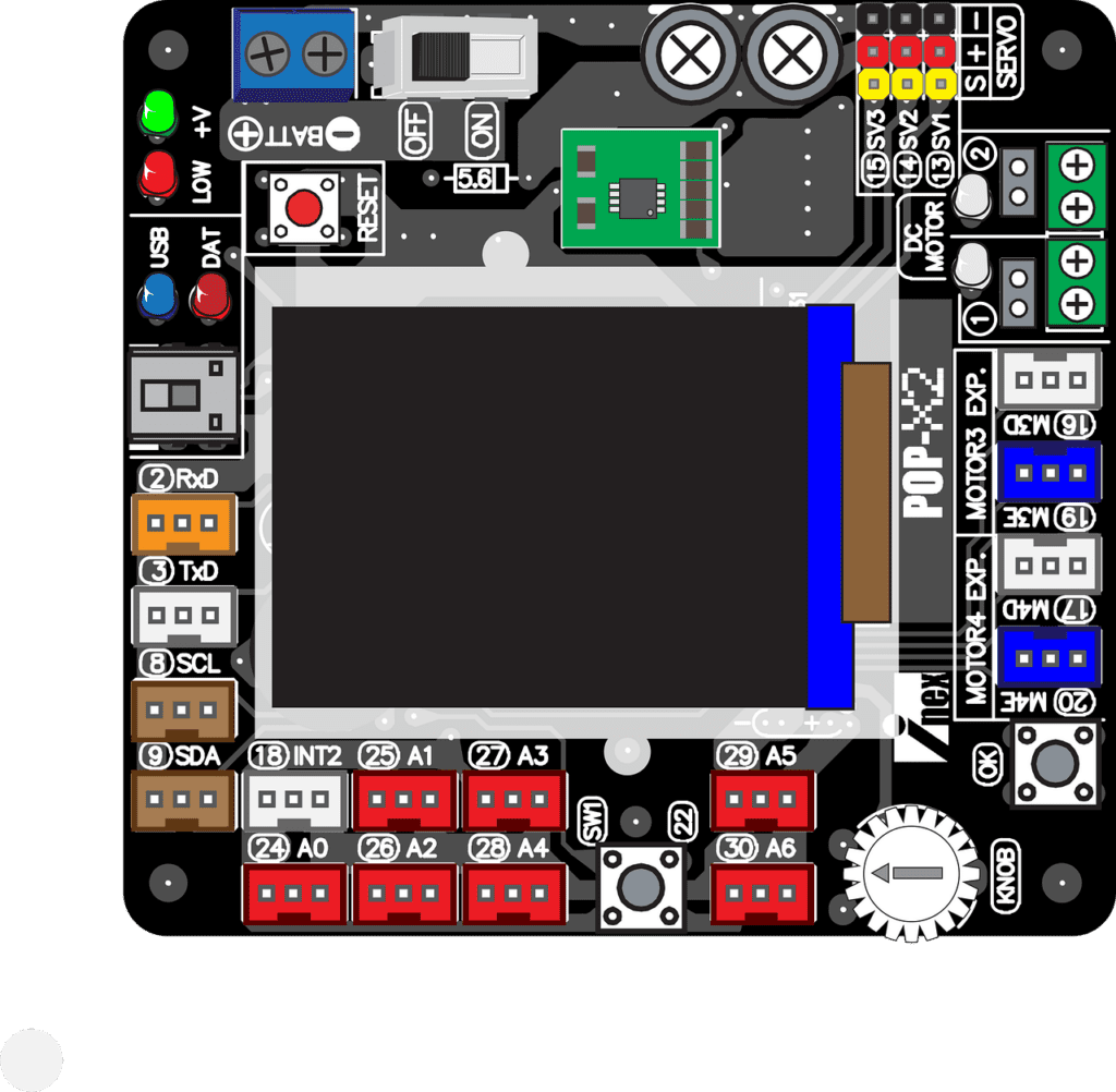


A number of substances, including as fiberglass, epoxy, and , are used to create PCBs. Copper is etched onto the surface of the substrate to create the conductive paths. Solder is used for attaching the parts ts the PCB.
Single-layer, double-layer, or multilayer PCBs are all possible. While double-layer PCBs contain two conducting layers, single-layer PCBs only have one. More than two conducting layers are included on multilayer PCBs, which are often employed in sophisticated electrical components.
PCB Full Form: History
Early Development (1900s): The idea of a published circuit dates lower back to the early twentieth century. The earliest known patent for a broadcast circuit board changed into filed in 1903 through Albert Hanson, who designed a easy circuit board with conductive patterns.
Initial Commercial Use (Twenties): The first industrial use of PCBs commenced inside the 1920s. Paul Eisler, an Austrian engineer, is frequently credited with inventing the present day PCB in 1936. His design become used in radio device.
World War II Advancements (Nineteen Forties): During World War II, the improvement and use of PCBs advanced substantially. The generation was used to create more reliable and compact digital circuits for military applications.
Post-War Expansion (Fifties): After the struggle, PCBs have become extra extensively used in consumer electronics. The 1950s noticed the creation of computerized production strategies, which made PCBs more inexpensive and available.
Introduction of Multi-Layer Boards (Sixties): In the 1960s, the development of multi-layer PCBs allowed for more complicated and compact circuit designs. This innovation enabled the creation of more state-of-the-art digital gadgets.
Surface-Mount Technology (Nineteen Eighties): The Eighties noticed the significant adoption of surface-mount era (SMT), which allowed additives to be set up at once onto the floor of the PCB, similarly reducing length and growing production performance.
Advanced Designs and Materials (2000s-Present): In latest many years, PCBs have developed with advanced materials and designs, such as bendy and high-frequency PCBs. Innovations in PCB era maintain to guide the development of an increasing number of complex and miniaturized digital devices.
PCB Full Form: Feature
| Feature | Description |
|---|---|
| Conductive Pathways | Copper traces etched onto the board to electrically connect components. |
| Substrate Material | Base material (e.g., FR4, flexible polymers) providing structural support. |
| Component Mounting | Methods include through-hole, surface-mount, and embedded components. |
| Layer Types | Single-layer, double-layer, and multi-layer boards for varying complexity. |
| Thermal Management | Design elements like heat sinks and vias to manage heat dissipation. |
| Design Flexibility | Options for rigid, flexible, or rigid-flex designs to suit different applications. |
| Manufacturing Techniques | Includes photolithography, etching, and laminating for precise patterning. |
PCB Full Form: Types
Single-Sided PCB: Contains only one layer of conductive fabric on one side of the substrate. It’s the best and maximum price-powerful type, utilized in primary electronic devices.
Double-Sided PCB: Features conductive layers on both facets of the substrate, bearing in mind greater complicated circuits and higher element density. Components may be set up on both facets.
Multi-Layer PCB: Consists of more than one layers of conductive fabric separated by insulating layers. This type helps complex circuits and is used in superior digital gadgets, including computers and smartphones.
Flexible PCB: Made from flexible substances like polyimide, allowing the board to bend or fold. This kind is used in packages where space is confined or components want to be installed in uncommon shapes.
Rigid-Flex PCB: Combines rigid and bendy PCB sections within the identical board. This type offers the blessings of each inflexible and bendy PCBs, frequently used in complex packages like medical devices and aerospace systems.
High-Frequency PCB: Designed to handle high-frequency indicators with specialized substances and production techniques to limit signal loss and interference. Common in RF (radio frequency) and microwave packages.
Metal-Core PCB: Features a metallic base layer, generally aluminum or copper, to enhance warmth dissipation. This kind is used in applications requiring green thermal control, inclusive of LED lighting.
PCB Full Form: Advantages
| Advantage | Description |
|---|---|
| Compact Design | PCBs allow for a compact and organized arrangement of electronic components. |
| Reliability | Provides consistent and reliable electrical connections, reducing the risk of faulty connections. |
| Ease of Assembly | Simplifies the assembly process by providing a predefined layout for components. |
| Reduced Size and Weight | Enables the creation of smaller and lighter electronic devices. |
| Cost-Effective | Reduces manufacturing costs due to automation and mass production capabilities. |
| Improved Performance | Enhances electrical performance by minimizing interference and signal loss. |
| Thermal Management | Can incorporate thermal management features like heat sinks and vias to manage heat dissipation. |
PCB Full Form: Disadvantages
| Disadvantage | Description |
|---|---|
| Design Complexity | Designing complex PCBs can be challenging and require specialized knowledge and software. |
| Cost for Prototyping | Initial costs for PCB prototyping and setup can be high, especially for custom designs. |
| Fragility | PCBs can be brittle and prone to damage from physical stress or impact. |
| Heat Sensitivity | Some PCBs and components may be sensitive to high temperatures during soldering or operation. |
| Limited Flexibility | Rigid PCBs are not suitable for applications requiring flexibility or bending. |
| Signal Integrity Issues | High-frequency designs may experience signal degradation if not properly designed. |
| Environmental Concerns | Manufacturing and disposal of PCBs can pose environmental challenges due to hazardous materials. |
PCB Full Form: Limitations
Design Constraints: Complex designs can be difficult to create, specifically for complicated or excessive-density circuits. Detailed layout and format work are required to make certain capability and reliability.
Cost of Customization: Custom or low-volume PCBs can be expensive to provide because of setup and production charges. This can be a barrier for small-scale or experimental tasks.
Size and Space Limitations: While PCBs allow compact designs, there are nonetheless barriers on how small or densely packed components may be, which could have an effect on the overall layout and performance.
Heat Management: High-electricity or high-frequency circuits can generate great heat, which might not be successfully managed by means of trendy PCBs with out extra thermal control solutions.
Mechanical Fragility: PCBs may be brittle and susceptible to bodily harm from effect, bending, or vibrations, that may compromise their integrity and capability.
Signal Integrity Issues: In excessive-frequency applications, preserving signal integrity may be tough. Issues which include sign interference, crosstalk, and impedance mismatches need cautious layout considerations.
Environmental Impact: PCB manufacturing and disposal can involve unsafe substances and chemical substances, raising issues about environmental effect and recycling challenges.
PCB Full Form: Characteristics
Layer Structure: PCBs will have extraordinary layer structures, inclusive of single-sided, double-sided, and multi-layer configurations. Multi-layer PCBs provide extra complexity and higher element density.
Conductive Paths: They feature etched copper lines that create electrical pathways between additives, ensuring right connectivity and sign flow.
Substrate Material: PCBs are constructed on a non-conductive substrate, normally crafted from materials like FR4 (fiberglass-strengthened epoxy resin) or flexible polymers. The desire of substrate affects sturdiness and versatility.
Component Mounting: Components can be set up the usage of numerous strategies including through-hollow, floor-mount generation (SMT), or a combination of each. This influences the board’s assembly and functionality.
Thermal Management: PCBs can also contain capabilities like warmth sinks, thermal vias, or copper pours to manage heat dissipation and make sure reliable operation of high-strength components.
Design Flexibility: PCBs may be designed in inflexible, bendy, or rigid-flex codecs, taking into account a number of applications from wellknown electronic devices to complex and space-confined environments.
Manufacturing Precision: The production process includes unique techniques like photolithography, etching, and soldering to gain correct and dependable circuit styles and connections.
Anatomy of a PCB: Layers and Components
The anatomy of a PCB (printed circuit board) is composed of several layers, each with its own function. The most common layers are:
- Conductive layers: These layers are made of copper and contain the traces that connect the electronic components together.
- Dielectric layers: These layers insulate the conductive layers from each other. They are typically made of fiberglass or epoxy.


- Silkscreen layer: This layer is printed on top of the board and contains text and symbols that identify the components and pathways.
- Solder mask layer: This layer is printed on top of the board and protects the conductive pathways from solder.
- Vias: These are holes that connect the conductive layers to each other.
Manufacturing Process of PCBs
| Step | Description |
|---|---|
| Design | The PCB is designed using computer-aided design (CAD) software. The CAD software creates a digital file of the PCB, which is then used to manufacture the board. |
| Photolithography | A photoresist is applied to the substrate material. The photoresist is a light-sensitive material that is used to create a pattern on the substrate. A laser or UV light is used to expose the photoresist, which creates a pattern of exposed areas. |
| Etching | The exposed areas of the photoresist are etched away, revealing the copper underneath. The copper is then etched away using a chemical solution. The remaining copper is the conductive pathways of the PCB. |
| Layering | If the PCB is multilayer, the layers are stacked together and bonded. The layers are bonded using heat and pressure. |
| Drilling | Holes are drilled in the PCB for the components. The holes are drilled using a CNC machine. |
| Silkscreen | A layer of silkscreen is applied to the PCB. The silkscreen contains text and symbols that identify the components and pathways. |
| Solder mask | A layer of solder mask is applied to the PCB. The solder mask protects the conductive pathways from solder. |
| Assembly | The components are placed on the PCB and soldered in place. The components are soldered using a soldering iron or a reflow oven. |
| Testing | The PCB is tested to ensure that it functions properly. The PCB is tested using a variety of methods, including electrical testing, visual inspection, and functional testing. |
Conclusion
FAQs
Q1: What is the PCB full form?
A: PCB full form is Printed Circuit Board. It is a board used to mechanically support and electrically connect electronic components.
Q2: What are the main functions of a PCB?
A: The primary functions of a PCB are to provide mechanical support for electronic components and to create electrical connections between them through conductive pathways.
Q3: What materials are used to make a PCB?
A: Common materials used in PCBs include FR4 (fiberglass-reinforced epoxy resin), flexible polymers, and metal cores, depending on the application and requirements.
Q4: What are the different types of PCBs?
A: PCBs come in various types, including single-sided, double-sided, multi-layer, flexible, rigid-flex, high-frequency, and metal-core PCBs.
Q5: What is a multi-layer PCB?
A: A multi-layer PCB consists of multiple layers of conductive and insulating materials stacked together, allowing for more complex and compact circuit designs.


